


Noshok 920 Series RTD Transmitter series
NOSHOK List price: $129.06
NOSHOK Type 10L Reduced Pressure, Non-Metallic Lower, Bolted,200 PSI Replaceable Diaphragm Seals-Noshok
NOSHOK List price: $244.80
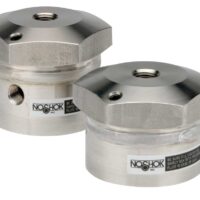
Noshok Type 29 High Volumetric Displacement, Non-Replaceable Diaphragm Seals
Type 29 High Volumetric Displacement, Non-Replaceable Diaphragm Seals
- An off-line seal with a threaded connection and all welded, all metallic housing design that does not utilize an o-ring or gasket
- Can be used for remote mounting of pressure instrument(s) with capillary, see options & accessories below
- Designed with a larger diameter diaphragm for higher displacement capability
- A variety of upper and lower housing and diaphragm materials are available to suit most applications
- A flushing port is available to clean wetted areas and prevent process media build up
Specifications | Instruments | O-Ring Temperature Limits | Diaphragm Pressure and Temperature Limits | Bottom Housing Material Maximum Pressure and Temperature Limits | Application | Additional Information | Prop 65 Warnings | Limitations Which Apply Are | Options and Accessories
Prop 65 Warnings
Prop 65 Warnings |
 WARNING: This product can expose you to chemicals including Nickel, which is known to the State of California to cause cancer and birth defects or other reproductive harm. For more information go to www.P65Warnings.ca.gov WARNING: This product can expose you to chemicals including Nickel, which is known to the State of California to cause cancer and birth defects or other reproductive harm. For more information go to www.P65Warnings.ca.gov |
Options and Accessories
Cooling Elements |
|
Diaphragm Seal Fill Options |
|
Distribution Manifolds |
NOSHOK’s Distribution Manifolds connect multiple instruments to one diaphragm seal, eliminating multiple connections that lead to possible leak paths. |
Plain and Armored Capillaries |
|
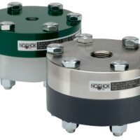
Noshok Type 29 High Volumetric Displacement, Non-Replaceable Diaphragm Seals
Type 29 High Volumetric Displacement, Non-Replaceable Diaphragm Seals
- An off-line seal with a threaded connection and all welded, all metallic housing design that does not utilize an o-ring or gasket
- Can be used for remote mounting of pressure instrument(s) with capillary, see options & accessories below
- Designed with a larger diameter diaphragm for higher displacement capability
- A variety of upper and lower housing and diaphragm materials are available to suit most applications
- A flushing port is available to clean wetted areas and prevent process media build up
Specifications | Instruments | O-Ring Temperature Limits | Diaphragm Pressure and Temperature Limits | Bottom Housing Material Maximum Pressure and Temperature Limits | Application | Additional Information | Prop 65 Warnings | Limitations Which Apply Are | Options and Accessories
Prop 65 Warnings
Prop 65 Warnings |
WARNING: This product can expose you to chemicals including Nickel, which is known to the State of California to cause cancer and birth defects or other reproductive harm. For more information go to www.P65Warnings.ca.gov |
Options and Accessories
Cooling Elements |
|
Diaphragm Seal Fill Options |
|
Distribution Manifolds |
NOSHOK’s Distribution Manifolds connect multiple instruments to one diaphragm seal, eliminating multiple connections that lead to possible leak paths. |
Plain and Armored Capillaries |
|